Designing Fully Redundant Infrastructure: Physical and Logical Layers Explained
High availability (HA) ensures systems remain operational despite component failures. By implementing redundancy at both physical and logical layers, organizations can minimize downtime and enable seamless maintenance.
This guide outlines a fully redundant architecture designed for critical enterprise workloads.
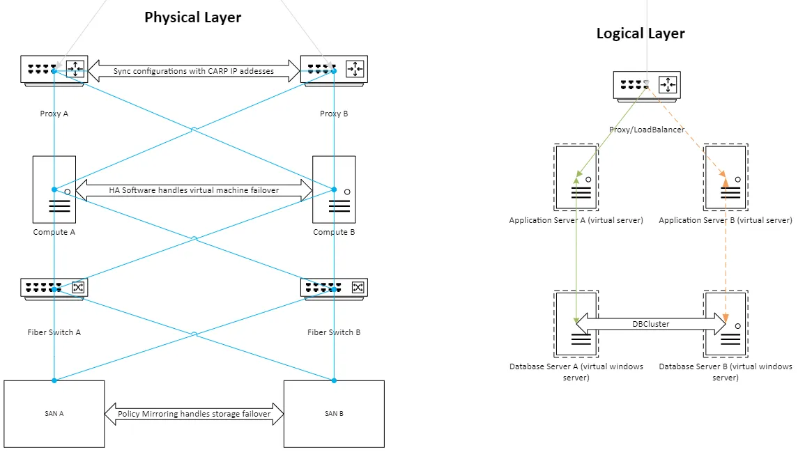
The Physical Layer
To ensure full redundancy, every hardware component is deployed with a companion device. Interconnections utilize distinct cabling standards for specific traffic types:
- Network Traffic: Blue lines represent standard TCP/IP communications (CAT5e or better) for management and user access.
- Storage Traffic: Orange lines represent Fiber Channel connections for high-speed, reliable data transmission.
- Power: Each device connects to independent power sources to prevent single-point electrical failures.
Compute Nodes
Compute nodes (hosts) run the hypervisor (e.g., vSphere) on mirrored internal drives.
- Virtualization: Hosts form a cluster where HA software automatically migrates and restarts virtual machines on healthy nodes if a hardware failure occurs.
- Capacity: The cluster must have sufficient reserve capacity to handle the workload of a failed node without performance degradation.
Storage Area Network (SAN)
Storage redundancy is critical. While software-defined storage (vSAN) is an option, physical SANs offer robust hardware-level replication.
- Mirroring: SANs utilize policy-based mirroring to replicate data across storage units in real-time.
- Connectivity: Compute nodes connect to SAN switches via multipath Fiber Channel. Zoning on switches ensures secure and redundant paths between hosts and storage arrays.
The Logical Layer
Traffic automatically routes to healthy nodes via VIP health checks.
Capacity maintained during single node failure.
The logical layer defines how data and requests flow through the infrastructure. This design decouples the service availability from the underlying operating system state, allowing for zero-downtime maintenance.
Load Balancing & Proxies
All incoming requests hit the load balancer or proxy layer first.
- Virtual IP (VIP): Technologies like pfSense use CARP to present a single virtual IP address to clients.
- Failover: If the primary load balancer fails, the backup assumes the VIP instantly.
- Distribution: Traffic is distributed to application servers based on health checks and load metrics.
Application Servers
Application servers (e.g., IIS) process the business logic.
- Statelessness: ideally, these servers store no unique local data.
- Shared Data: Any persistent content should reside on shared network storage or the database.
- Updates: Administrators can patch and reboot Server A while Server B handles all traffic, then repeat for Server B.
Database Clusters
Data integrity requires stricter synchronization than application code.
- Clustering: MSSQL Clustering (or similar technologies) ensures transactional consistency between database nodes.
- Sync: Data is synchronously replicated to ensure the secondary node has an up-to-date copy at all times.
Summary
This multi-layered approach to redundancy achieves two primary goals:
- Resilience: Hardware failures (switches, cables, servers, storage) do not interrupt service.
- Maintenance: Systems can be patched and updated during business hours without downtime.
Note: High availability is not a backup strategy. While it protects against hardware failure, it does not prevent data corruption or ransomware. A separate, immutable, off-site backup strategy remains essential for disaster recovery.